Manual Calculation Of True Position Formula
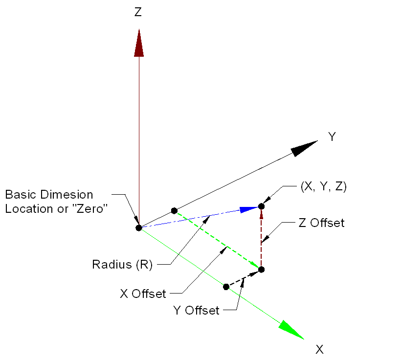
The formula for calculating true position is true position tolerance = 2 x SQRT(XVAR 2 + YVAR 2). In this instance, SQRT refers to a square root, XVAR refers to the amount of deviation from the basic dimension found in the X-axis, and YVAR refers to the amount of deviation from the.
Hello,Customer is looking for a cpk on a measurement for positional tolerance of a hole.The problem I have with this is the nominal measurement is 0 and tolerance is 0.25 but it's a position tolerance, it's not +/- 0.25 (I can't measure negative position).Does anyone know how to make this or should I make 2 cpk's, one for each axis?Reports come from a CMM and if I have to make two I would like to know if anyone knows the formula for calculating the tolerance for each axis. Example (Y - Nominal=3, measured=2.976/Z - Nominal=1, measured=1.014 / position=0.055).I can't find a formula to make this work, should I just try various tolerances until both me and my customer is satisfied (I'm joking here).Thank you in advance,Emil. You have several problems here. Cp/Cpk is based on several assumptions, the most critical of which is that the data are normally distributed.In the position scenario, a hole center could deviate +/- from the target location in any direction. However, the Position tolerance uses an absolute value resulting in a decidedly skewed distribution (probably a folded Normal distribution). This violates the critical assumption of normality making a Cp/Cpk value meaningless.Your other idea of calculating a Cp/Cpk for the separated X/Y coordinates would resolve the normality issue because the +/- X/Y locations are often Normally distributed, but introduces another problem. You now have a SQUARE tolerance zone instead of a CIRCULAR zone.
This means that your Cp/Cpk would be overstated.And what about bonus tolerances? There are several approaches to dealing with this, but no standard agreement, and each approach gives quite different results.Need I continue? Emil - most customers that have positional tolerances are looking for the vector approach to the two (or 3) axes. Mathematically this solves the square problem you get by trying to calculate an index for each axis.
Emmyd's spreadsheet is correct for that application.However, now you have the 'one sided', non-normal distribution problem that 'modern thinking' on capability indices abhors. AIAG does have an out for this:AIAG PPAP 4th Edition, 2.2.11.5 Processes with One-Sided Specifications or Non-Normal Distributions:NOTE: The above mentioned acceptance criteria (2.2.11.3) assume normality and a two-sided specification (target in the center).When this is not true, using this analysis may result in unreliable information.These alternate acceptance criteria could require different type of index.(Many thanks to Bob Doering for continually pointing this out)My suggestion is to ask your supplier quality rep. The only way I have ever done it that sat with me well was to calculate a principal variation. (Think principal stress). Basically, in order to get position you do have an 'x' and 'y' measurement. With no guarantee that your maximum noise will be aligned with either x or y.
So you take the standard deviation of the x's and the standard deviation of the y's and calculate the square root of the sum of the squares to get the 'principal' standard deviation. Think the hypotenuse of a right triangle. This is the maximum variation. Your tolerance is then your positional tolerance and you use this worst case standard deviation in a regular Cp/Cpk calculation. As others have said, this doesn't account for bonus tolerance. To do that, one could just use the RFS tolerance (because if THAT is capable, it would be capable with the bonus tolerance).
OR you could increase the bonus by an average bonus tolerance. Again - it's not well defined. That sounds like a good approach, Emmyd.
I think I might do that as a pass 2, unless I had a spreadsheet all set up. Because to do that you would need all the diameters for each measurement as well. If pass 1 was OK against RFS constant, then it would also be OK against the inclusion of bonus tolerance. If I had a dismal failure against RFS, I know I need work.
If I was a near miss, I could very much see recalculating INCLUDING bonus with the method you have outlined. It would be a lot more cyphering.(I say this because many times the diameters aren't available. Which is (my opinion) ridiculous, but them's the data I get sometimes.).

The basic formula for True Position is 2 x the square root of the deviation in one axis squared + the deviation in the other axis squared.True Position = 2√ Deviation in X² + Deviation in Y²It's hard to convey a good example of the formula with the font limitation of this forum. However, the X & Y axis’ are for a feature measured in the Z axis plane.
If you measure in the X axis plane, you would substitute the X² with Z². If you measure in the Y axis you would substitute the Y² with Z².Subsequently, if there is a MMC modifier in the call out you would be allowed bonus tolerance.
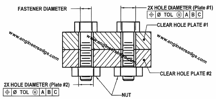
As long as you do NOT have any modifiers (meaning the tolerance, as well as the datums are at RFS (Regardless of Feataure Size)), you can do the math by hand. Even a modifier on the tolerance is still quite easy to calculate.The moment you at a modifier on the datums though, things get complicated immediately. I agree with Mat, it can take pages to figure it out by hand.I have done many experiements using modifiers on datums using PC-DMIS V4.1, comparing it to hand estimates. Generally, I think that they calculate it correctly.
You have to use the new Xactmeasure GD&T to get it right. I believe it does not work using the legacy dimensioning.Jan.
3 Dimensional True Position Calculation


The basic formula for True Position is 2 x the square root of the deviation in one axis squared + the deviation in the other axis squared.True Position = 2√ Deviation in X² + Deviation in Y²It's hard to convey a good example of the formula with the font limitation of this forum. However, the X & Y axis’ are for a feature measured in the Z axis plane. If you measure in the X axis plane, you would substitute the X² with Z². If you measure in the Y axis you would substitute the Y² with Z².Subsequently, if there is a MMC modifier in the call out you would be allowed bonus tolerance. This is a good 2 dimensional true position calculator. Thanks for all the good replies guys. I screwed my knee up last Thursday and just got back to work today.Wish I could post a pic but can't.
I'll try it this way:the call out is: t/p dia.015 to f d & eWe make landing gear for large airplanes so everything is round and cyclindrical(sp).The part is shaped like a cyclinder, open on one end (the face on that end happens to be datum -e-), closed on the other end with a lug w/an approx. 4.5' hole running perpendicular to the cyclinder. Clear as mud?The C/L of the cyclinder is datum -d- with the face of the lug being designated as datum -f. All datums are listed as RFS.It was my understanding that you simply added the third datum to the equation as Matt has shown. My partner in crime here on the 2nd shift was under the impression that there was a lot more to it than that.Thanks again.
True Position Calculator Excel Formula
I can always count on you guys for the help.
